• Home
  • Rovers
  • Subdivisions
    • Mechanical
    • Electronics & Software
    • Bioscience
    • Design and Logistics
  • Teams
    • Current Team
    • Alumni
  • Competitions
  • Contact

Electronics and Software Subsystem

Controls

Autonomous

GUI

Wireless

Power Distribution and BMS

Controls

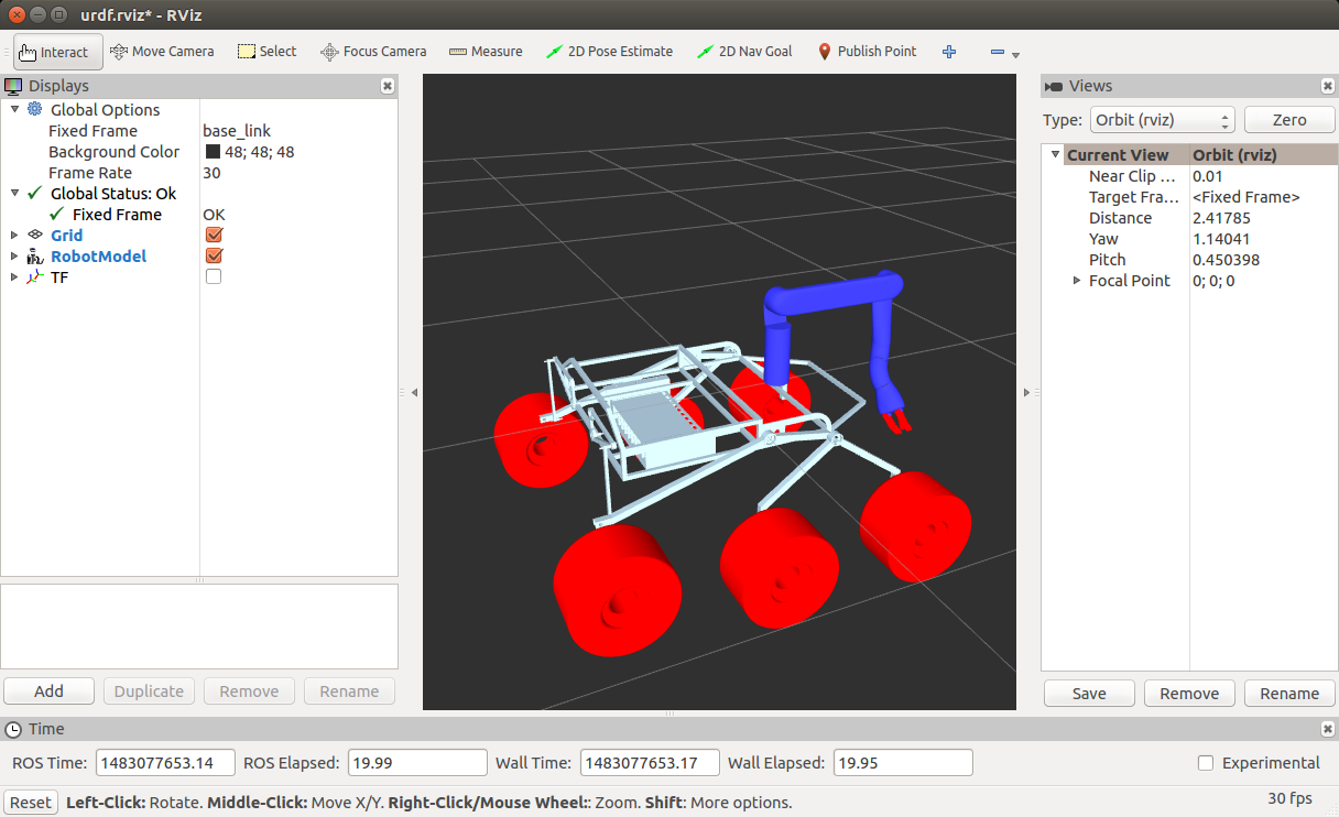
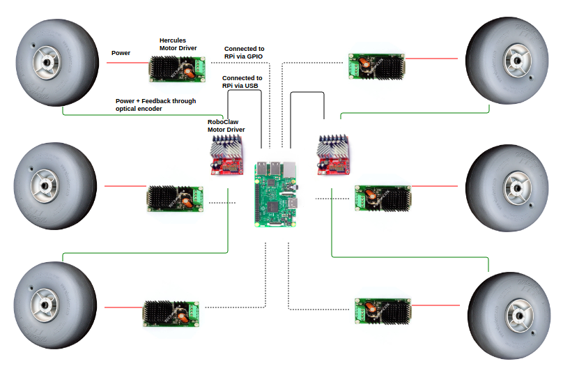
All 6 wheels are driven independently from GPIO pins of Raspberry Pi 3 in open loop, 4 steering wheels (Front and Rear) are steered using closed loop control .
Steering is controlled by Roboclaw Motor Drivers onto which we employ a Type II control system, to track ramp input , while drive is controlled by Hercules motor Drivers.
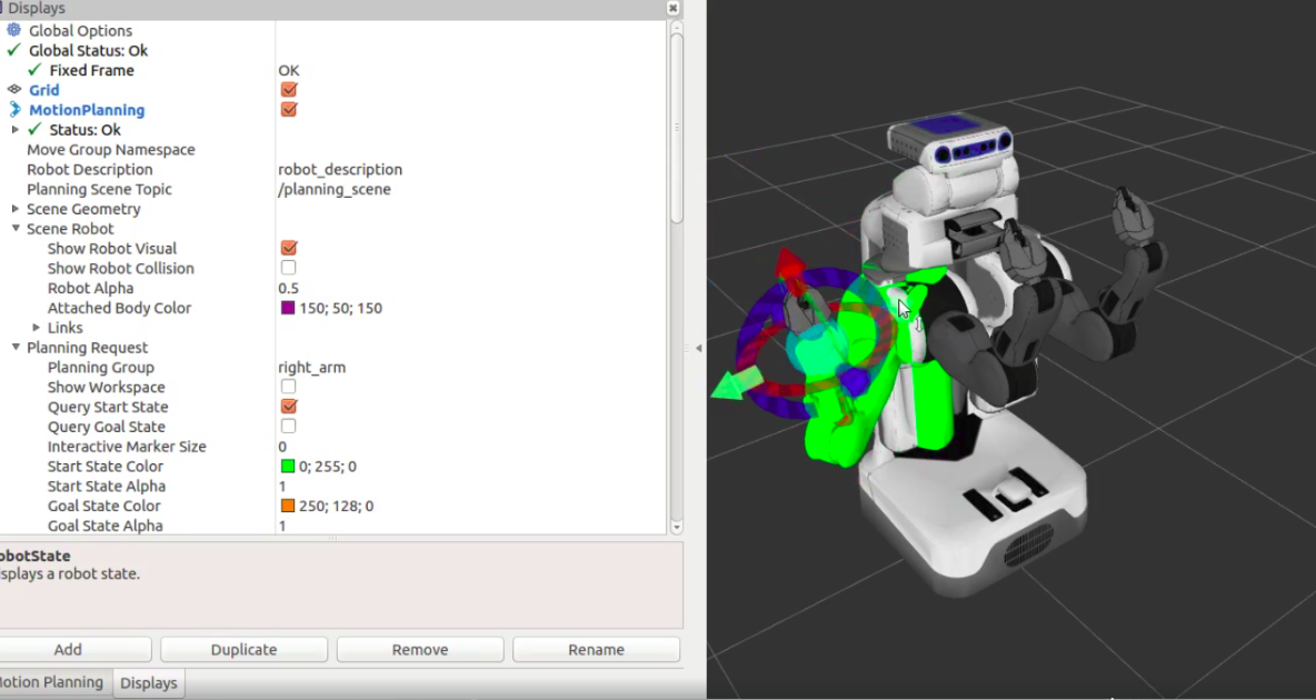
We are working towards getting a state space description of the same, so that we can employ Inverse Kinematics or LQR control for the arm, using Moveit! motion planning plugin .

Autonomous

Surrounding mapping is done using SLAM; requires a high-power LIDAR for visualising the map.
The whole system is up and running on Gazebo in a simulated environment and the algorithm is being improved for better performance. (video on right).
We are working to employ the algorithm on our smaller prototype of the rover first, and then later shift to main rover.

GUI

URDF Visualisation: As a first step towards automating the system, an URDF of rover (pic on left) was made, which helps us translate what rover is doing on field onto the GUI and autonomous node.
Plotting GPS data from APM module (pic on left): GPS lat long received from APM using mavros library is mapped onto RViZ aerialmapdisplay plugin using QT gui.
IP Camera interfacing with GUI: RTSP stream of IP camera is obtained using opencv and using ROS-OpenCV bridge, stream is converted to image message. The GUI widget ‘Image View’, is used to visualise the message.

Wireless

We are using commercial off-the-shelf PoE wireless bridges which operate in 5.6 GHz band , and have maximum EIRP of 36 dBm, compliant with FCC UNII-1 regulations.
These have been tested to give 1 km non-LOS range, and use adaptive channel selection techniques to shift to a different channel once the current channel starts degrading, to tolerate interference.
Video feed is obtained via IP cameras on board and telemetry is achieved by passing messages between ROS nodes.

Power

The entire rover will be powered by a 24 Volt custom battery pack consisting 3.7 Volts lipo cells.
24V - 12V and 24V - 5V DC-DC buck converters are used on a custom made PCB to distribute power for every components.
A Capacitor bank is used on the PCB to compensate for the effect of back EMF generated from the motors and actuators.
We are designing a Battery Management System for cell balancing and monitor the health of lipo cells during charging and discharging.